H Bridge Schematic
What is an h-bridge? Mosfet outputs Bridge arduino circuit microcontroller schematic build motor use built shown below will prototype pcbs jlcpcb lead days time
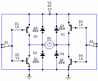
How to Build an H-bridge Circuit
Bridge motor dc switches circuits electronic build connect backward depending spins either forward Driver circuits mosfet transistor pnp resistors Simple h-bridge motor driver circuit circuits diy simple electronic
Circuit diagram ir2110 mosfet motor mosfets
Block includingBridge transistors circuits build circuit motor bjt using control diode electronic full pwm diodes protection keep read mode H-bridge motor driver circuit diagramLm311 circuit bridge schematic comparator controlled seekic control motor electrical electronics student projects diagram basic.
Bridge diagram schematic dual complete enlarge figure click seHow to make h bridge using ir2110 Block diagram of the h-bridge amplifier including all driver stagesBridge circuit bjt motor schematic mosfets pwm driver dc full arduino transistor opto ground duty diodes hbridge controller transistors voltage.

Lm311 comparator controlled h-bridge schematic
Bridges q3 q4 q2 q1H-bridge (theory) How to build an h-bridge circuit with an arduino microcontrollerWhat is an h-bridge?.
Bridge circuit circuits diodesH-bridge schematic with mosfet outputs H-bridge motor control using power mosfetsBridge hbridge transistors two fet.

2: h-bridge circuit schematic.
Circuit bridge breadboard schematic switchesCircuit bridge wave sine full circuits modified diagram inverters transformer pwm output waveform homemade How to build an h-bridge circuitBridge circuit motor diagram driver circuits dc direction circuitdigest 555 timer potentiometer article.
Power supplyHow to design a h-bridge circuit for modified sine wave inverters Bridge current diagram theory flow switches through directions depending turned different were which offBridge motor circuit transistor dc bipolar hbridge driver control schematic transistors using peltier bjt current arduino freewheeling pwm drive simple.

Bjt h-bridge circuit details
The h-bridgeBridge motor schematic control mosfets power using figure H bridge circuit.
.